Annotated attachments in isometric/spool drawings
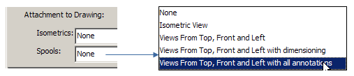
In Documents > Piping Isometrics > Tools > Options, the project administrator can define whether to attach annotated views to isometric and spool drawings. The standard view types are Isometric View, Views From Top, Front/SB, and Left/AFT.
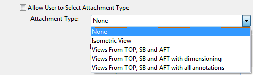
If Allow User to Select Attachment Type is selected, users can select the attachment type to use when geometries are exported from Plant Modeller to Piping Isometrics & Spools with Drawings > Create isometric/spool drawings.
If the option is not selected, then the administrator sets the Attachment Type to use, and all users in the project are enforced to use this type.
This setting is separate for isometrics and spools.
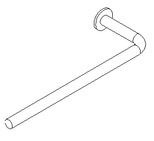
Isometric view
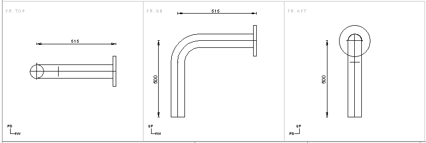
Views From Top, Front and Left or TOP, SB and AFT.
Views can be plain, with dimensioning or with all annotations. Views From Top, Front and Left or TOP, SB and AFT can be used in isometrics that include only one spool.
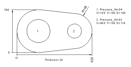
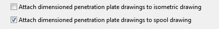
A multi-pipe penetration plate view can be attached to isometric drawings or spool drawings or both.
Drafting Style for multi-pipe penetration attachments
When multi-pipe penetration attachments are created, Plant Modeller uses a Drafting Style definition with a fixed name: MppAttchmentForIsosAndSpools. A default Drafting Style COS object with this name is automatically created into the library database when it is needed for the first time, if:
- The current user has a project administrator profile
- The action takes place at the master COS server
The project administrator is expected to customize the default style according to the needs of the user organization. Thus, the easiest workflow is to first create some multi-pipe attachments and then edit the created default Drafting Style object. See Drafting Styles.
See the following example of creating spools with annotated attachments.
Preconditions
-
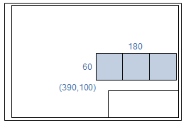
In Settings > 3D Attachment define the area for the 3D Attachments for spools. In the picture below, the lower left corner for the area is at (390,100), area width is 180, and height is 60.
-
Default spool ICGD must be selected in the settings.
In Plant Modeller
-
In the Piping isometrics tool of Plant Modeller, create an isometric group.
-
Select Drawings > Create isometric/spool drawings or Drawings > Update geometries of isometric/spool drawings.
-
Select the views to be attached to spools from the drop-down menu.
-
Select the isometrics to be created from the list and click OK.
-
Select Drawings > Work with isometric drawings to start the Piping Isometrics & Spools application.
In Piping Isometrics & Spools
-
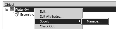
In the Piping Isometrics & Spools application, right-click an isometric drawing and select Spools > Manage from the menu.
-
Click Automatic Annotation and select the spools to be annotated from the list.
-
Click View and select the spool from the list.
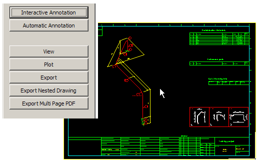
Note: The attachment can be manually relocated in the drafting space of the drawing. Choose Interactive Annotation or Edit drawing, select Drafting > Import/Export > Move 2D Import and relocate the attachment.